Popular Highlights
When only a watchmaker will do
Restoration of Omega Jump Seconds Clock
Measurement in Watchmaking
Thanks to all my friends at schaublinlathes@yahoogroups.com whose helpful critiques resulted in the high quality of the following information.
One of the most vexing requirements and demanding skills to acquire is accurate measurement. I struggled with this for years and have finally reached a point of "no drama" parts making.
A note and warning: For the sake of clarity, I express sub millimeter values as fractions (20/100mm). This hurts the brains of those who work daily in metric. To many Americans, metric is still a foreign language. In machining, Imperial values are always expressed in thousandths of an inch (thou); 100 thou means 1/10 inch. Absolutely clear. There is no similar convention in metric for indicating sub-millimeter values other than to use microns which would be absolutely foreign to those not used to metric nomenclature. So I use the nomenclature of 20/100 mm to indicate .20mm in order avoid ambiguity and as an assist to those whose eyesight may miss the decimal point.
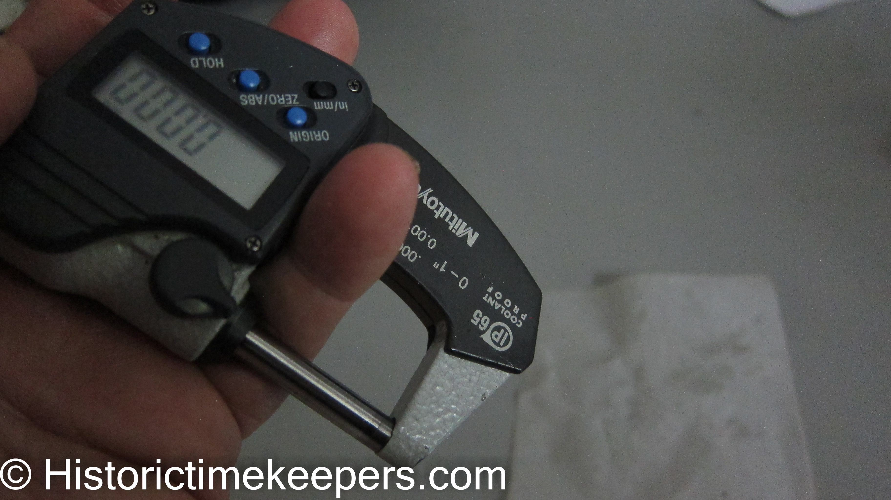
Every watchmaker should purchase a Mitutoyo Digital Carbide tipped one-inch micrometer and a Mitutoyo 6-inch digital caliper. Period. There is a role for the traditional micrometers that have a table for holding the object to be measured, but the Mitutoyos are the first instruments to buy. They are accurate and allow easy conversions of decimal inch to metric depending upon your tooling.
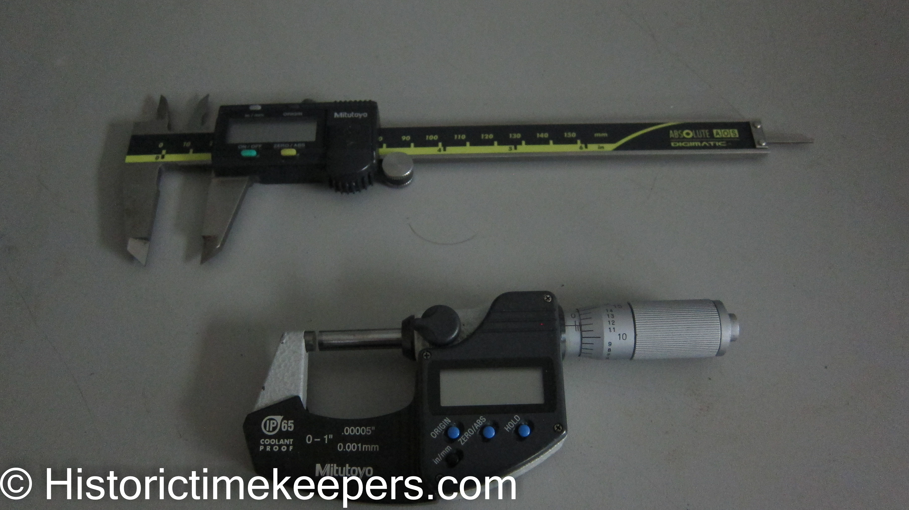
The micrometer cannot be beat for outside diameter (OD) measurements down to 50/100 mm. But once you get into pivot sized ODs (20/100 mm or less), the risk of breakage gets very high. There are other ways to measure small ODs.
The 6-inch caliper is also good at measuring most ODs and even many inside diameters (ID). Many people are unaware that the "tail" can be used as a depth gauge for measuring lengths, but I find the values to be unreliable because of the inconsistent way it is held on small pieces.
Machinery's Handbook Every watchmaker should get a copy. It is packed with info on how to set up bolt circles, threads, speed and feeds and whatever. I have the 18th edition which seems to suffice for those of us using manual machines.
The Traditional Bench Micrometer with the table has its uses; but I do not know that current pricing makes sense compared to the Mitutoyos.
Notes on Slide Rests as Measurement Instruments Slide rests that indicate actual table movement are great for milling attachments. In fact, I have a metric Schaublin slide rest for just that reason. But for turning, it is much easier for me to think in terms of diameters. You want actual movement for positioning a wheel/pinion cutting setup, measurement of actual table movements allows the setup to be handled like an XYZ coordinate measurement machine.
I also have a Schaublin slide rest that is scaled in 1 thousandths inches and which is coupled to a lead screw with a pitch (20 TPI) to yield a depth of cut 1/2 the indicated value. This allows me to work in diameters rather than radiuses. My Levin and Schaublin metric slide rests (which I use infrequently for the following reason) are scaled to show actual movement of the slide.
So having digital measurement devices that switch between units is very important to me.
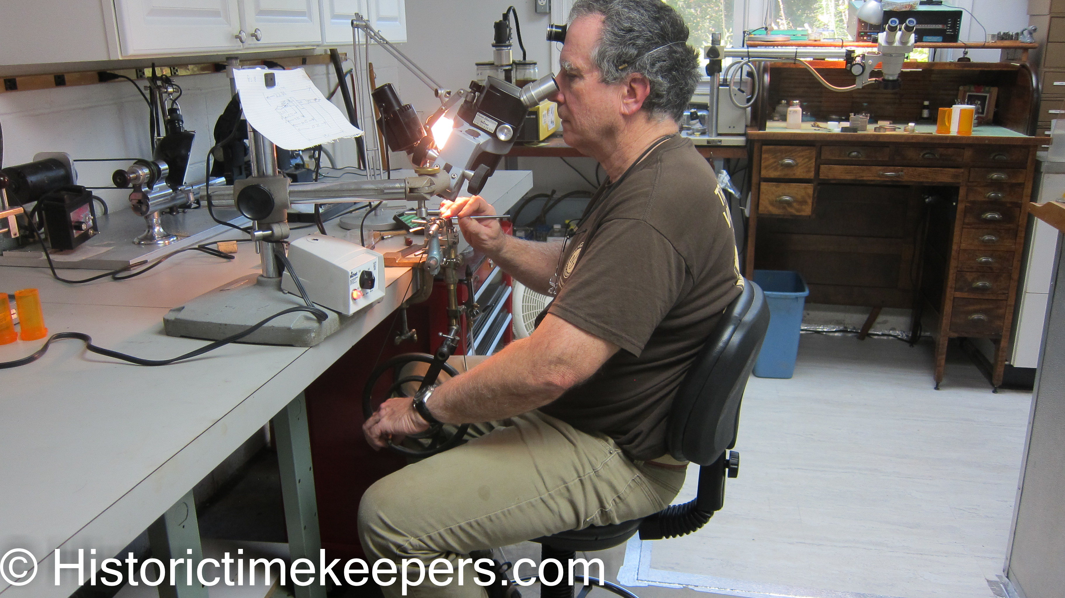
Below is my milling setup which uses my metric slide and vertical mill. Since all lead screws have the same pitch, they provide measurements of actual table movements and the cutter.
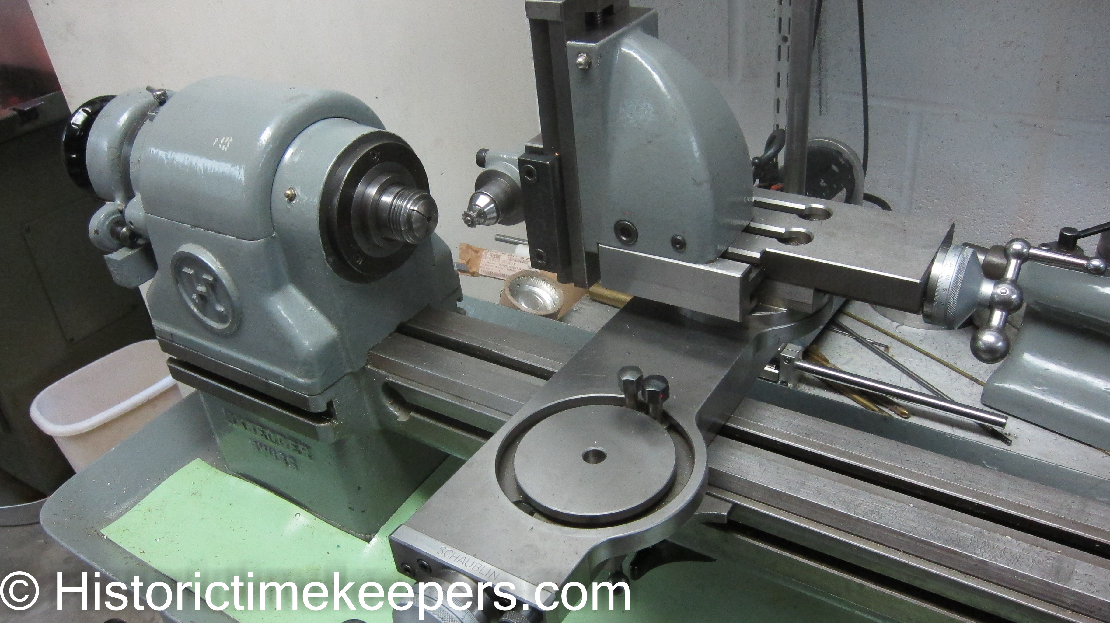
I had a metric vertical slide so I needed a metric slide rest. I wanted to avoid mixing between measurement units and remembering that my inch slide rest measured diameter removed (moved 1/2 the distance of the scale indication). Since I had to buy a slide rest anyway, I took advantage of an offer for a Schaublin Double Slide Rest. As you can see, the advantage is that I can put the milling attachment BEHIND the work so I can see what is going on. This setup can also be used as an XYZ coordinate machine for layout work!
OK, couple words on the two different transverse feed systems on slide rests. On all slide rests, the axial feed moves the distance as indicated on the scale. On Imperial slides, the axial lead screw is 10 TPI, which means each revolution of the crank moves the top slide 1/10 inch, or 100 thou. The transverse feed of many slide rests does exactly the same. The actual movement of the transverse slide is the distance indicated by the scale. On these, the scale indicates the actual depth of cut and refers to RADIUS of the turned part.
Some slide rests use a transverse feed that moves the slide 1/2 the distance as indicated by the scale. These use a lead screw of twice the pitch of the axial slide lead screw. The transverse feed scales in these slides indicate TWO times the actual feed! This means the scale value refers to DIAMETER. For me, this is a true advantage. I like to avoid sources of error whenever possible. I do not need to halve my calculated cut to get the diameter I intend. Secondly, my other slides are all metric. SO I KNOW when I am working with the Imperial slide rest, I am adjusting the transverse scale to OD. The older I get, the simpler I need things to be.
For example, the dials on my Schaublin inch slide rest are marked out the same. However, the lead screw for the transverse feed has twice the pitch (20 TPI) as the lead screw for the axial feed (10 TPI). Thus the indications on the transverse feed indicate 2 times the value of the actual table movement showing the diameter removed. The indications on the axial feed show direct movement of the tool, which allows precise measurement of the length of cut. To me, this combination is perfect for turning.
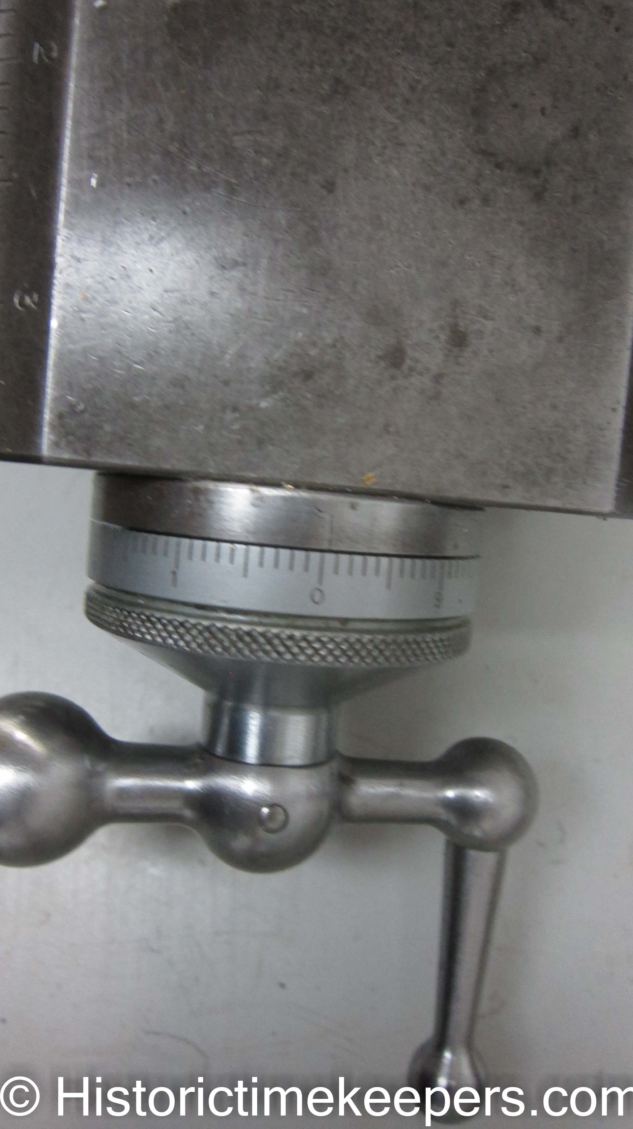
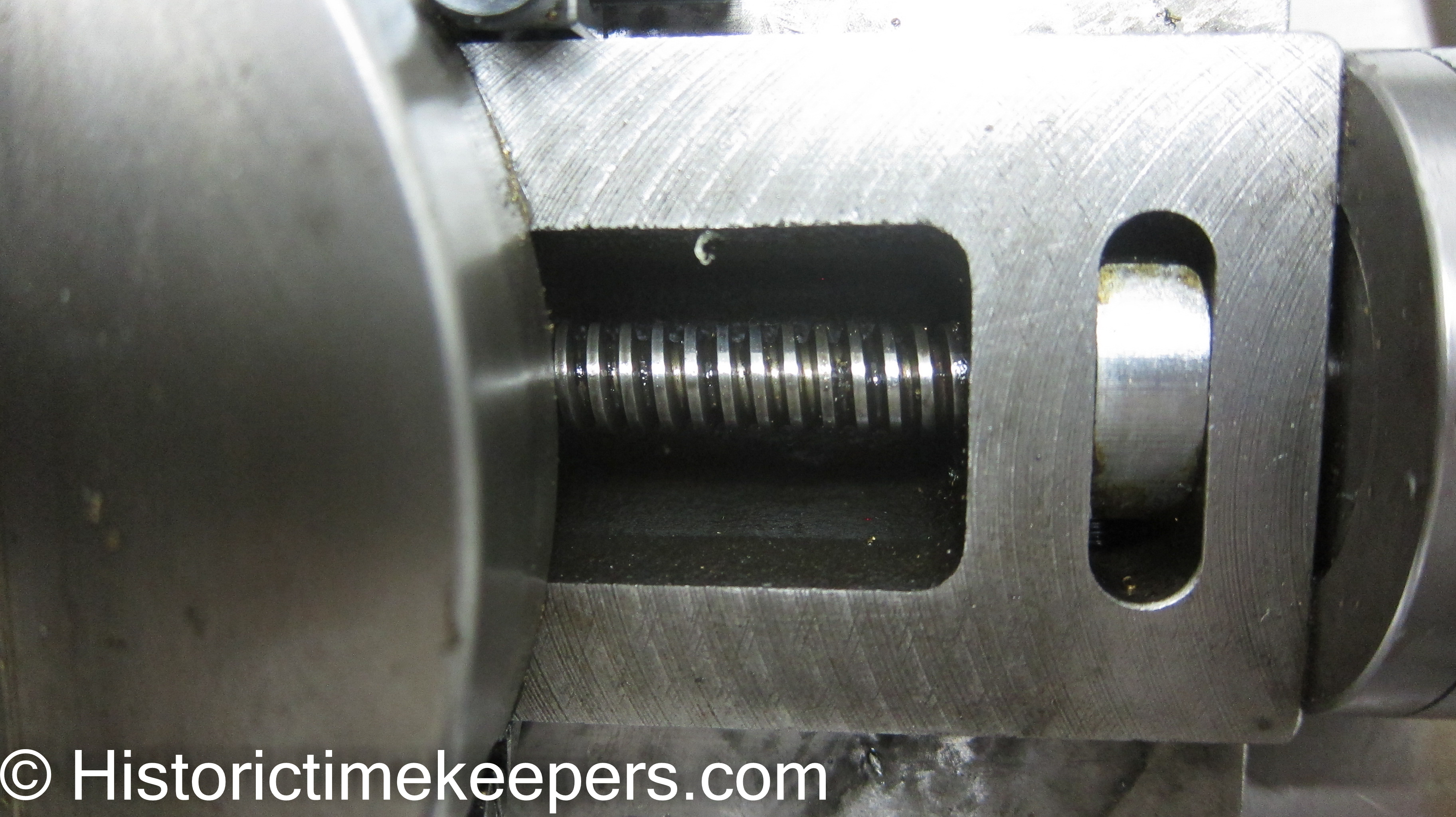
Above is the axial scale with 100 divisions and a lead screw which has a pitch of 10 TPI. This results in a top slide advance of 100 thou inches per revolution.
Below is the transverse lead screw again with 100 divisions but attached to a lead screw with pitch of 20 TPI. This results in an actual transverse table movt of 50 thou inch per revolution; which results in a work diameter change of 100 thou inch.
So the top slide (axial) moves twice as far per revolution as the bottom slide (transverse).
![]()
![]()
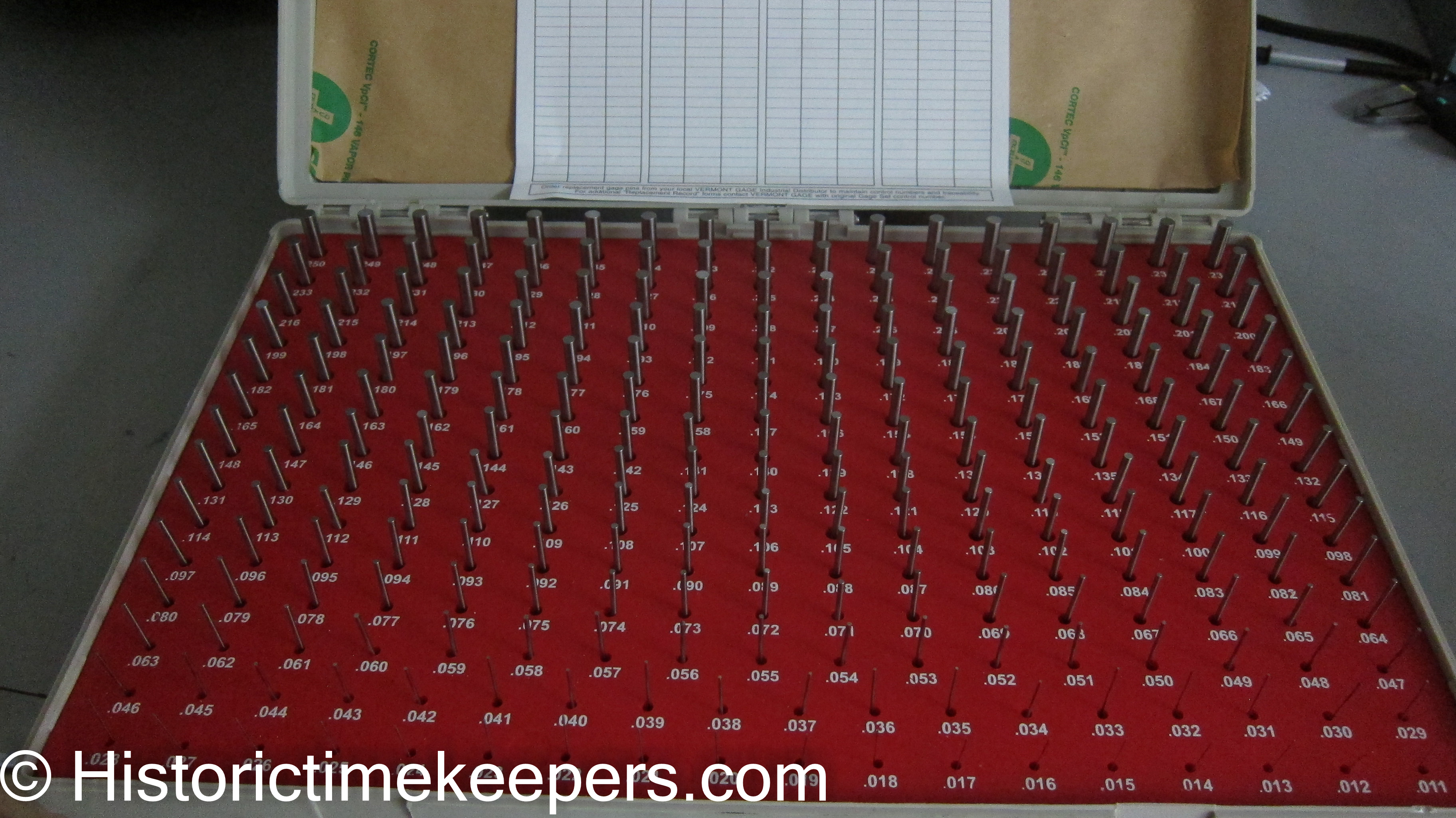
Measuring IDs accurately can be tricky. There are several ways to do this. One is to buy a Plug Gauge set for about $45 from MSC. These are sets of accurately sized wires that are tried in the bore until the next sized wire will not fit. Then you measure the wire with your micrometer. This works well for small holes.
For jewel holes it is useful to buy a set of jewel plug gauges or an OBAMA tapered jewel gauge. The former are still sold in sets by Bergeon and every European school trained watchmaker made their own set while in school. We made a couple in WOSTEP, each took about 3 hours and required a Jacot for final sizing. So these sets are a treasure when found.
For larger holes machinists use bore gauges, which are expanding ball shaped plugs. The ball is expanded in the bore until it is a sliding fit. This is then measured with the micrometer.
Measuring ODs accurately may seem straight forward until you start wondering how to accurately measure the OD of a wheel or pinion with an odd number of teeth or leafs.
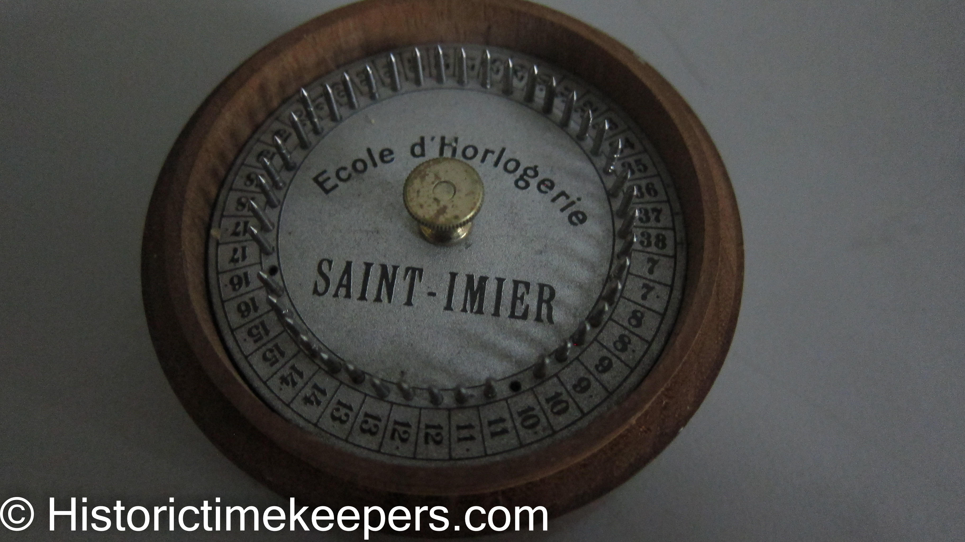
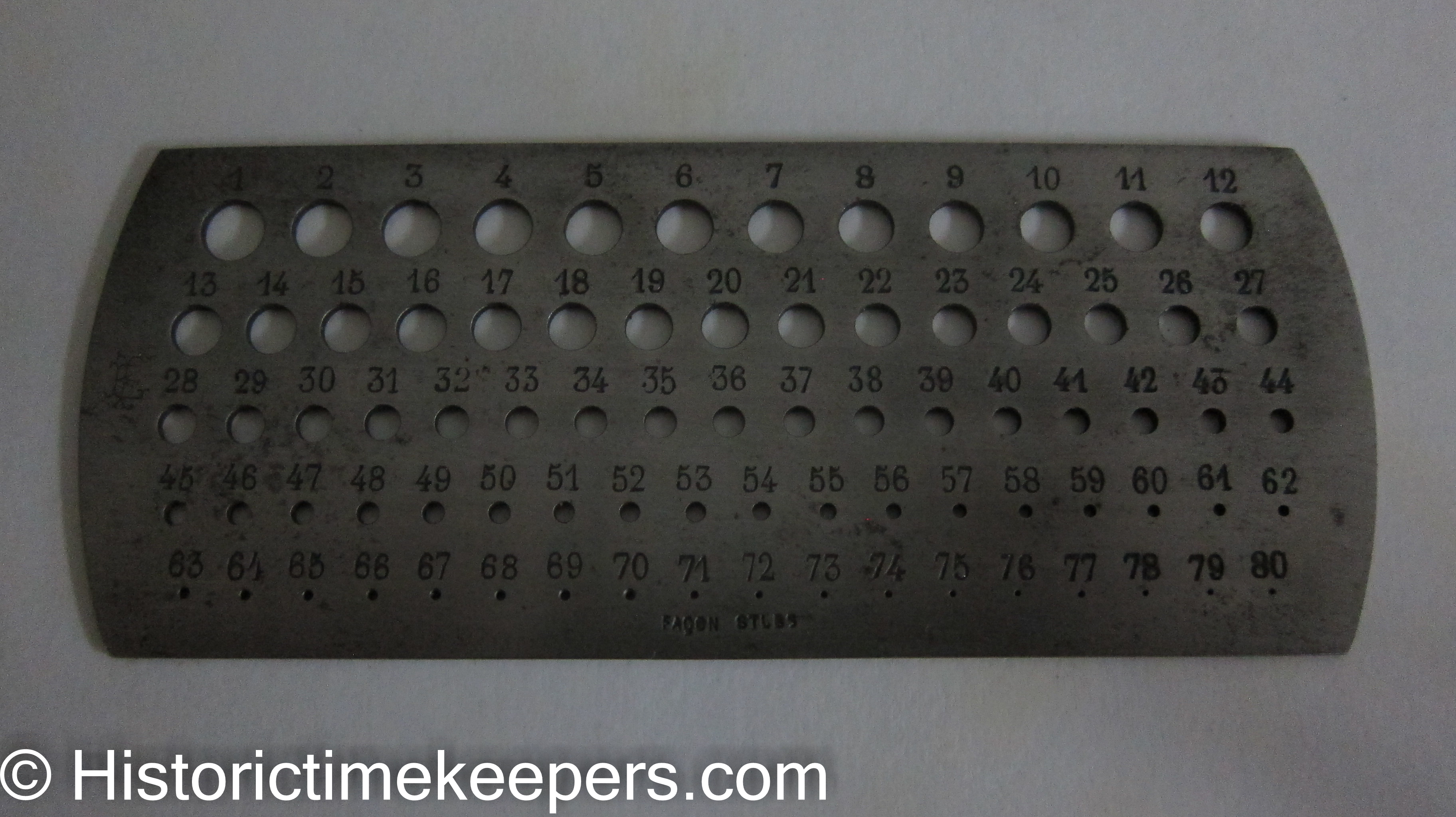
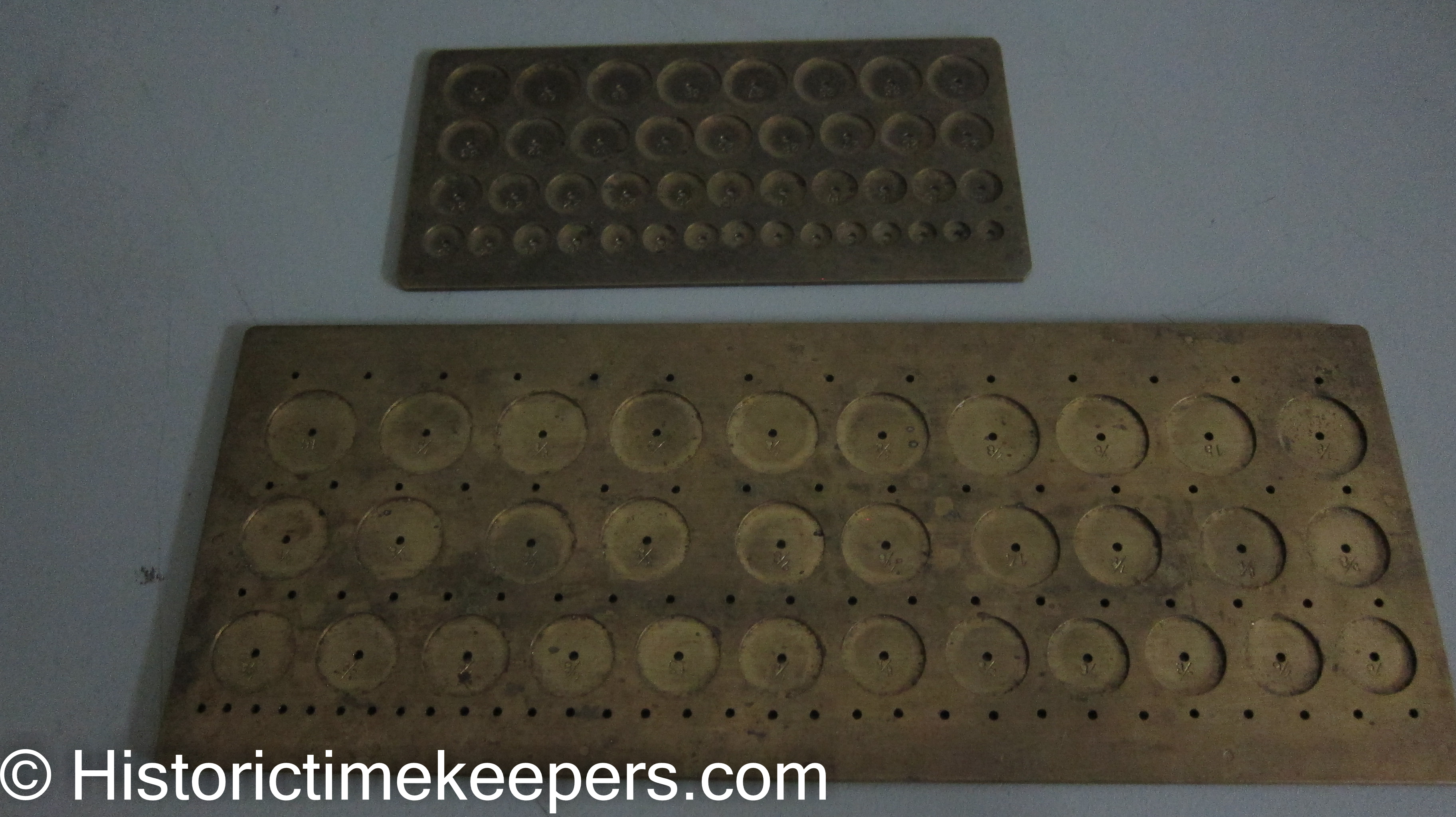
One very useful gauge is an American Drill Gauge. This is scaled in sizes of numbered drills (you know, 1-80 where 80 is the smallest). The other is the brass wheel gauges that show up from time to time. I have used drill gauge and leaf count to order pinion cutters from Thornton. The wheel gauge allows you to find the hole an odd numbered wheel fits, which can then be measured with the caliper.
Pivot gauges (Seitz) are VERY handy for measuring pivots. They previously cost between $5 and $20 used; now they are out of sight. I guess if I did not have one but I had a set of hole jewels, I would make one using my own friction jewels. Might take a day to make a nice one, but I just cannot see paying $150 for one.
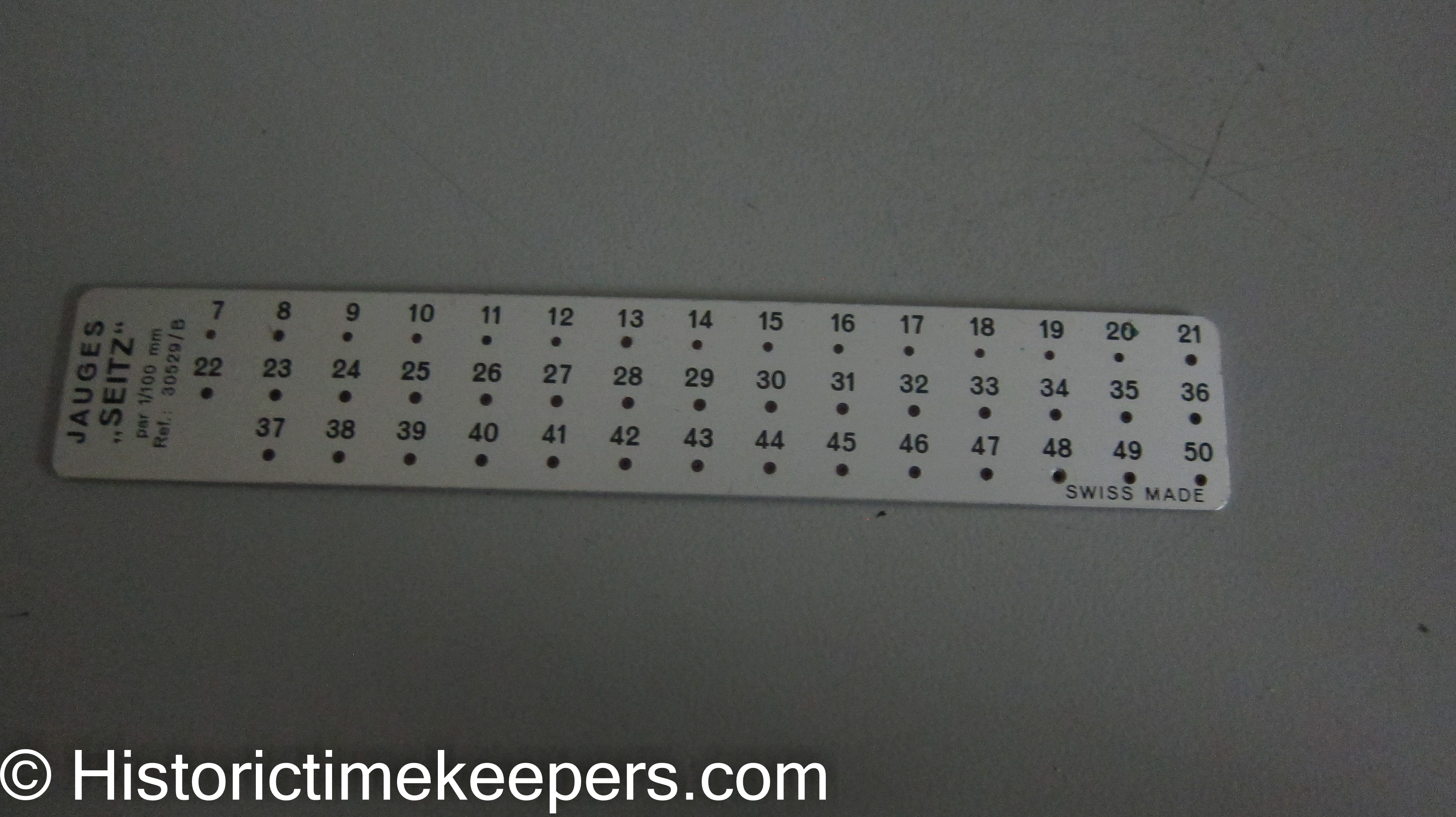
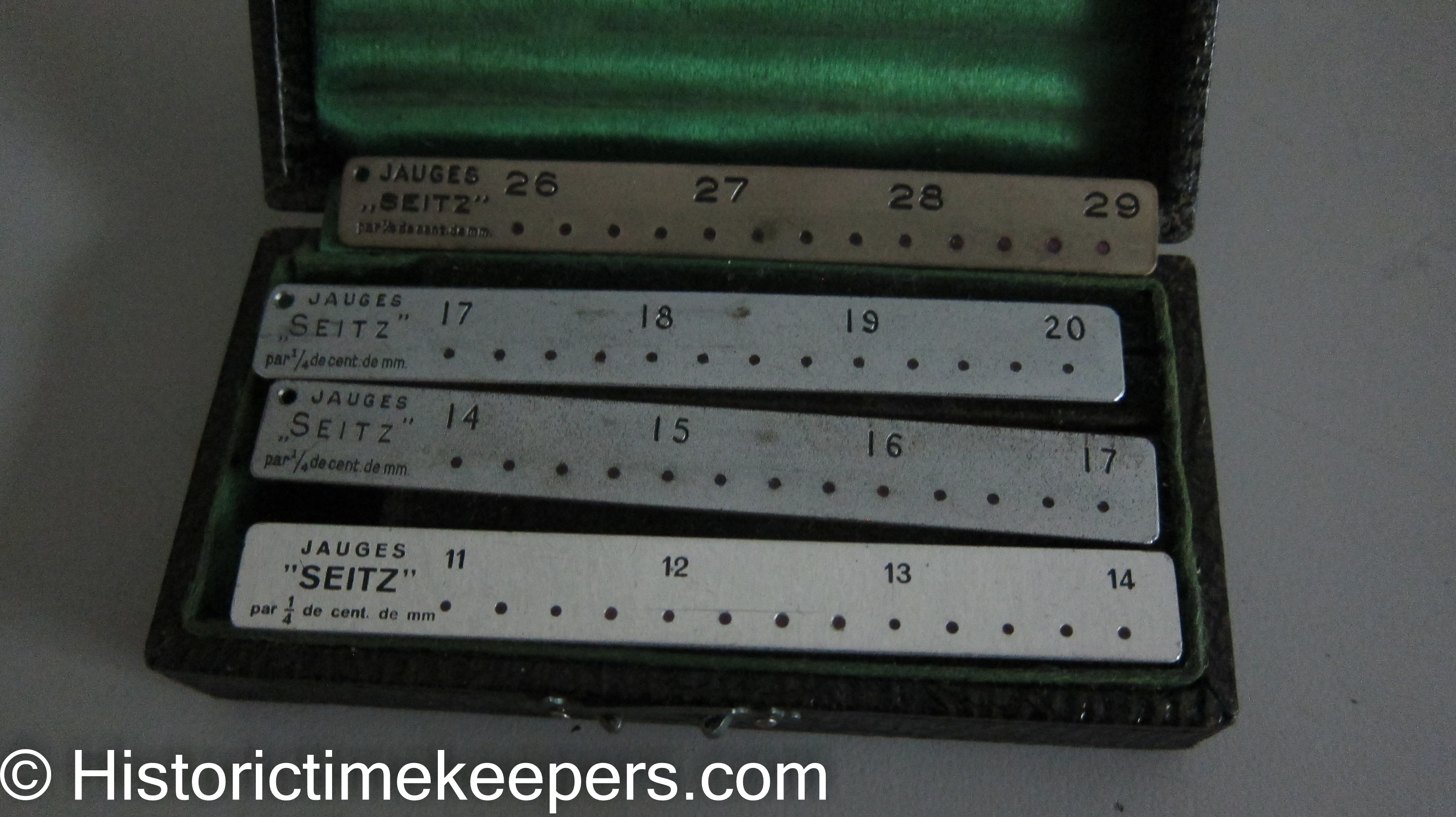
Also, be aware Seitz made jewels in 1/4 sizes to be sold and used in measurement sets. I have a set of 4 plates I purchased at a Swiss flea market.
Perhaps of interest is the Seitz balance staff breaking tool (they called it a pivot straightner). Often overlooked is that this tool uses 1/2 sized jewels. So it does have a use after all.
Do not be afraid of cracked jewels, and if you have the right size you can always replace them. But chipped jewels should be replaced or not used.
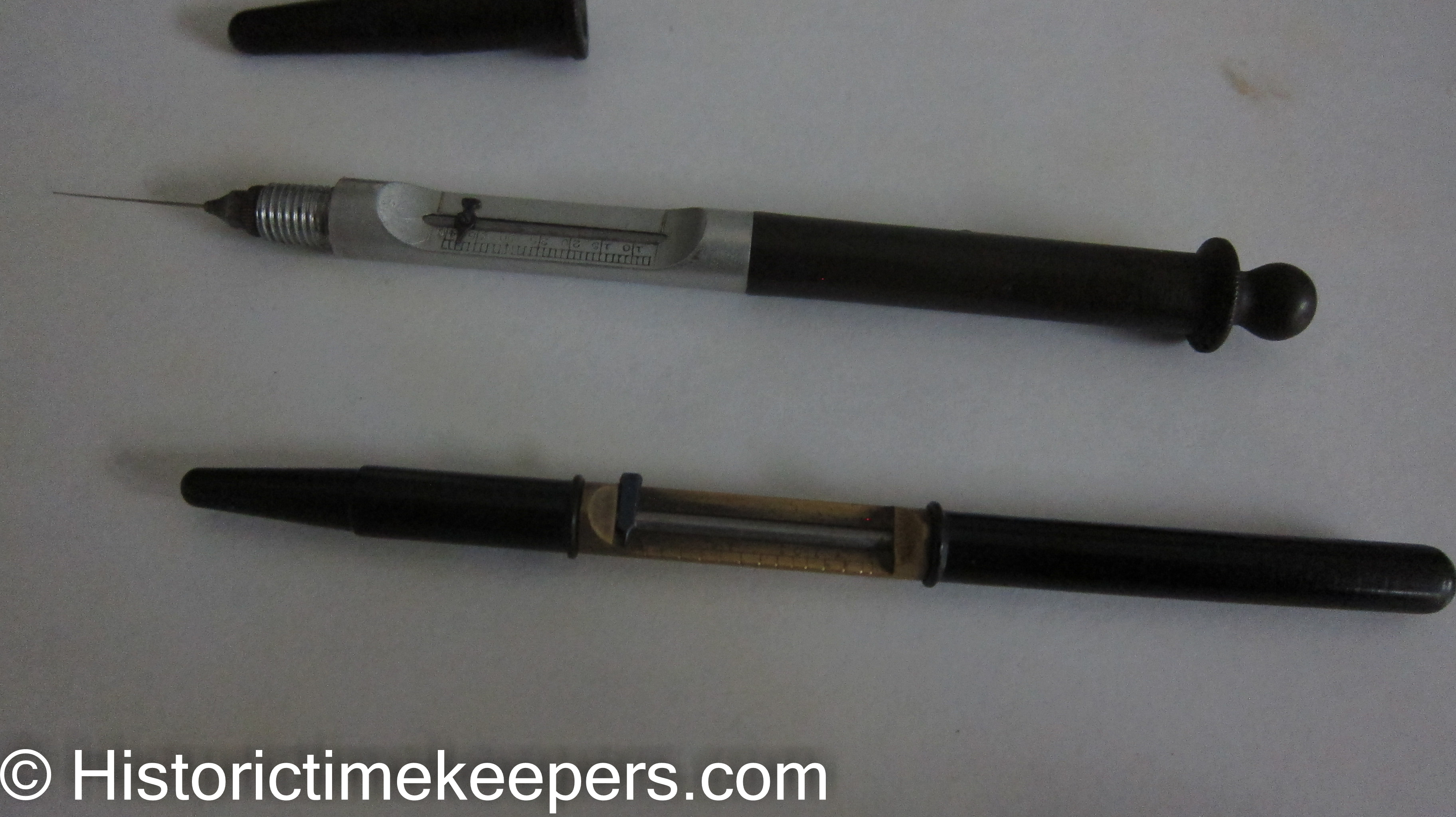
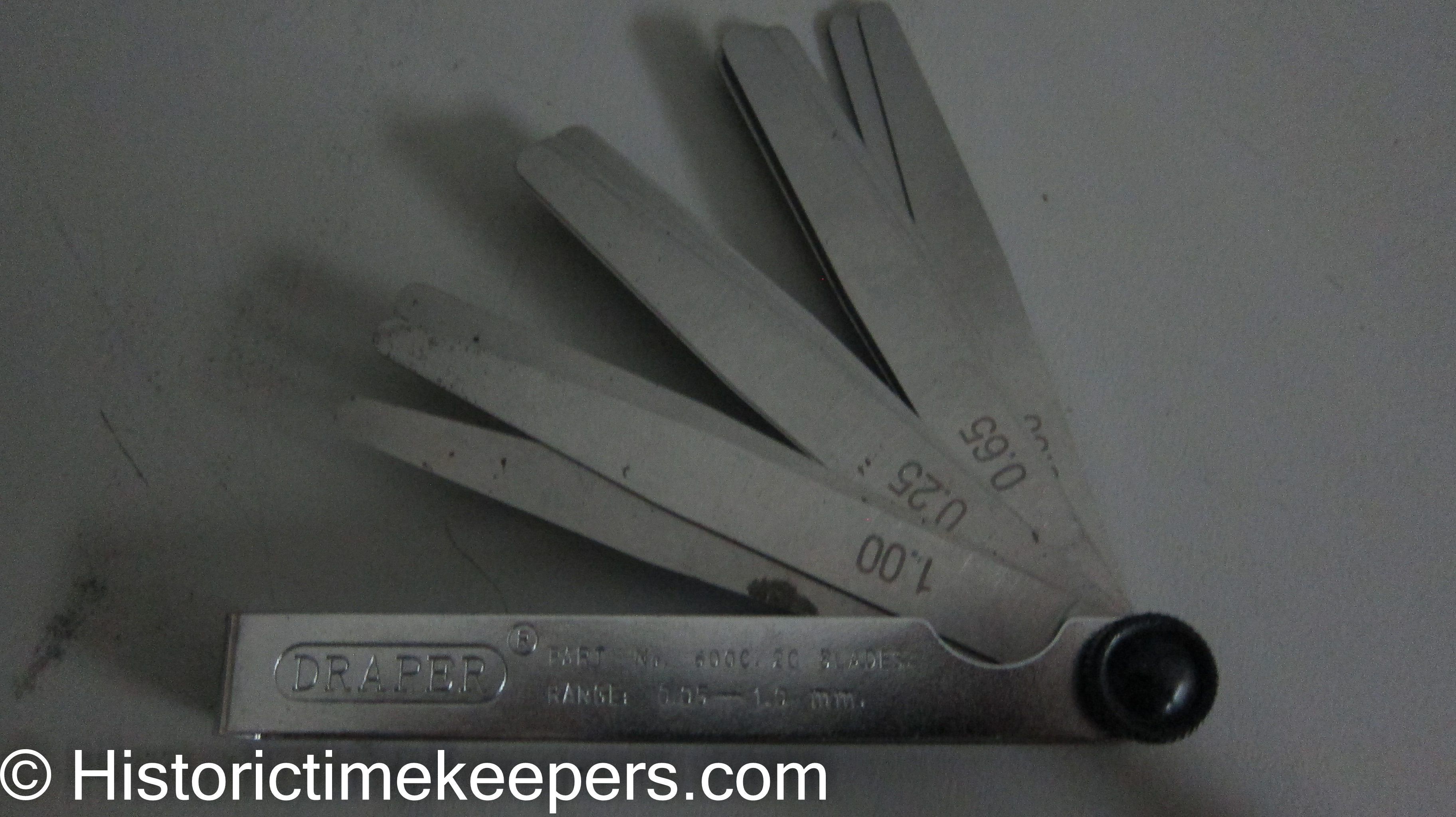
Measuring Lengths can be accomplished by several means. One is the tail of the caliper; but I find this to be an approximation at best. Most times I hit it; but most is not good enough. Next is the feeler or thickness gauge set. These are sold in sets of 5/100 mm increments. But they require that you become skilled in their use and usually require magnification. Used em for years but not so much any more. Requires holding the feeler against the work with one hand while setting your graver with the other; and if you are using a loupe it gets real tricky.
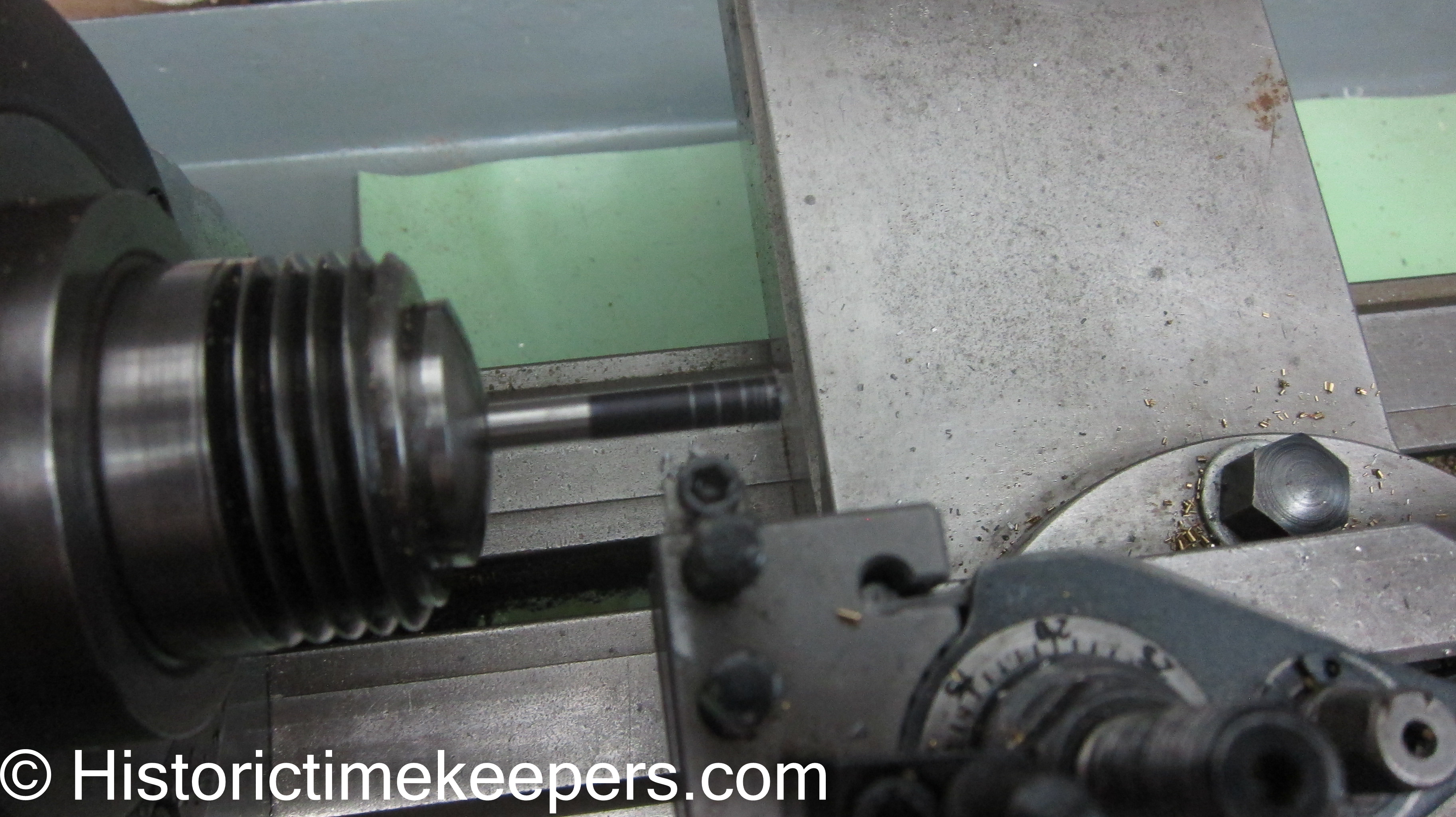
Below is an example of how a blank can be prepared on the lathe. The 45 degree cutter forms the point on the piece. Set the axial feed dial to zero. Back out the tool and then use the axial feed dial to to mark out your piece. Here, it is marked out in .10 inch increments FROM THE VERY TIP.
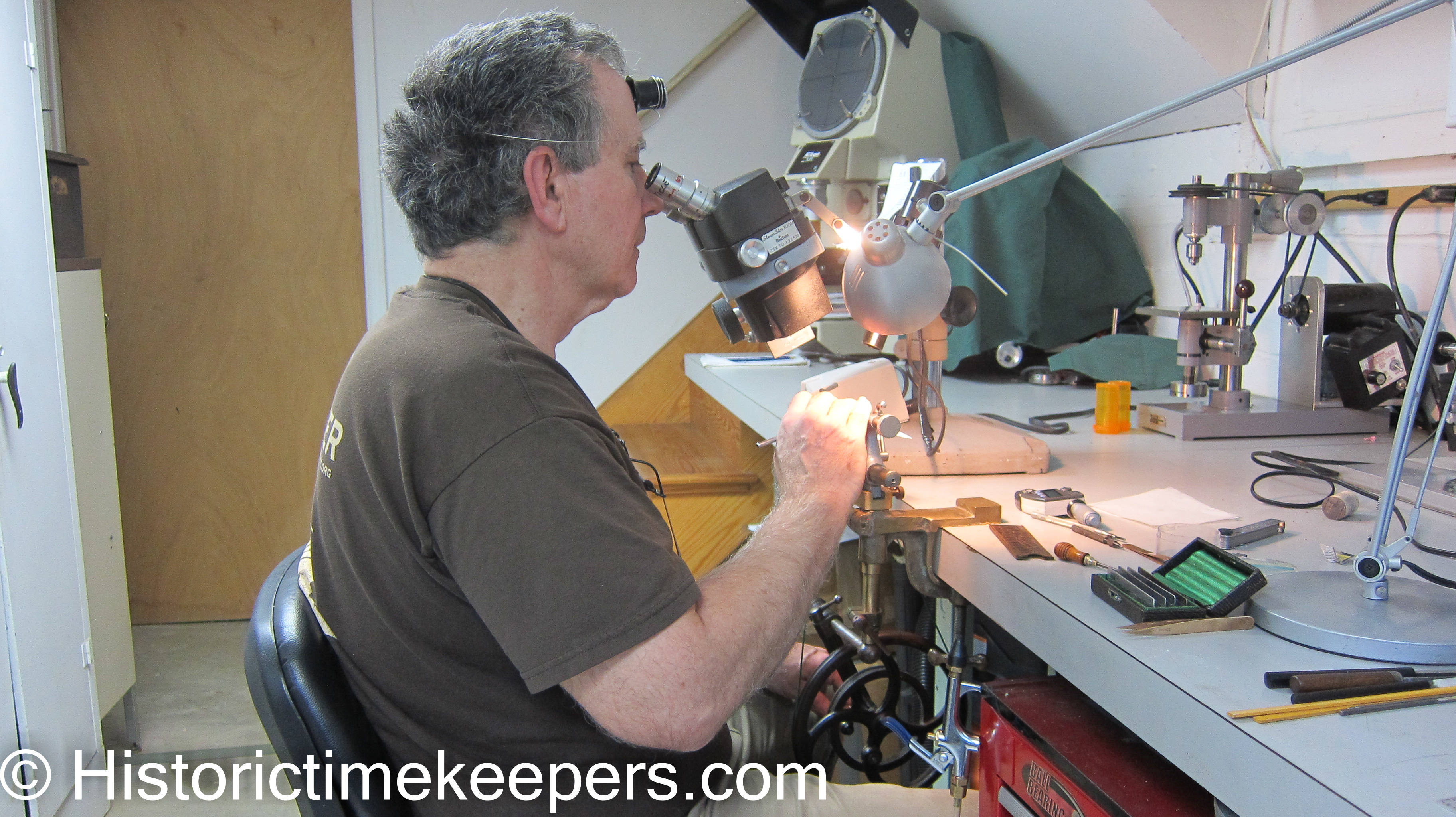
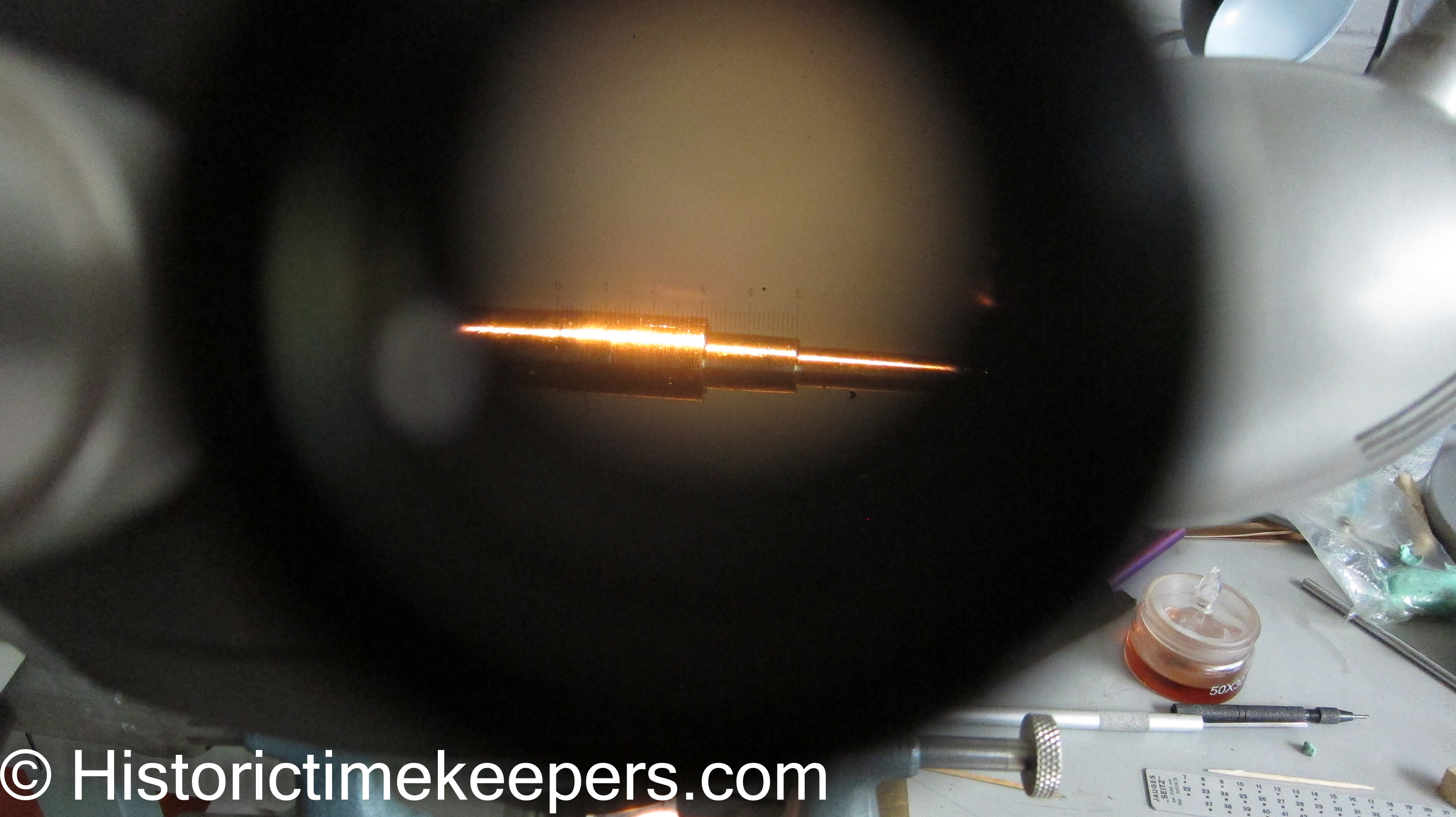
Microscopes can be used with great success and efficiency in measurement. Looking at my other pages you see I use microscopes for everything: at the bench, at the turns, at the 102 and for high mag inspection. What is NOT evident is that I use them for measurement, particularly of lengths while turning. Any zoom scope can be fitted with a measurement reticule in one of the eyepieces and the zoom control is then marked at the point where the reticule lines up with a slide marked off in 1/10 mm increments. The only other way of measuring lengths while turning is with the slide rest as previously discussed.
If you look closely, you will see the scale in the eyepiece just above the staff. It becomes very easy to see if you right click on the image and select "view image" or "view image in new tab" depending on your browser.
Another reticule is available for measuring radiuses. Beats trying to look at plug gauges under a loupe or microscope!
You can learn more about how I use microscopes by going to my Microscopes in Watchmaking page
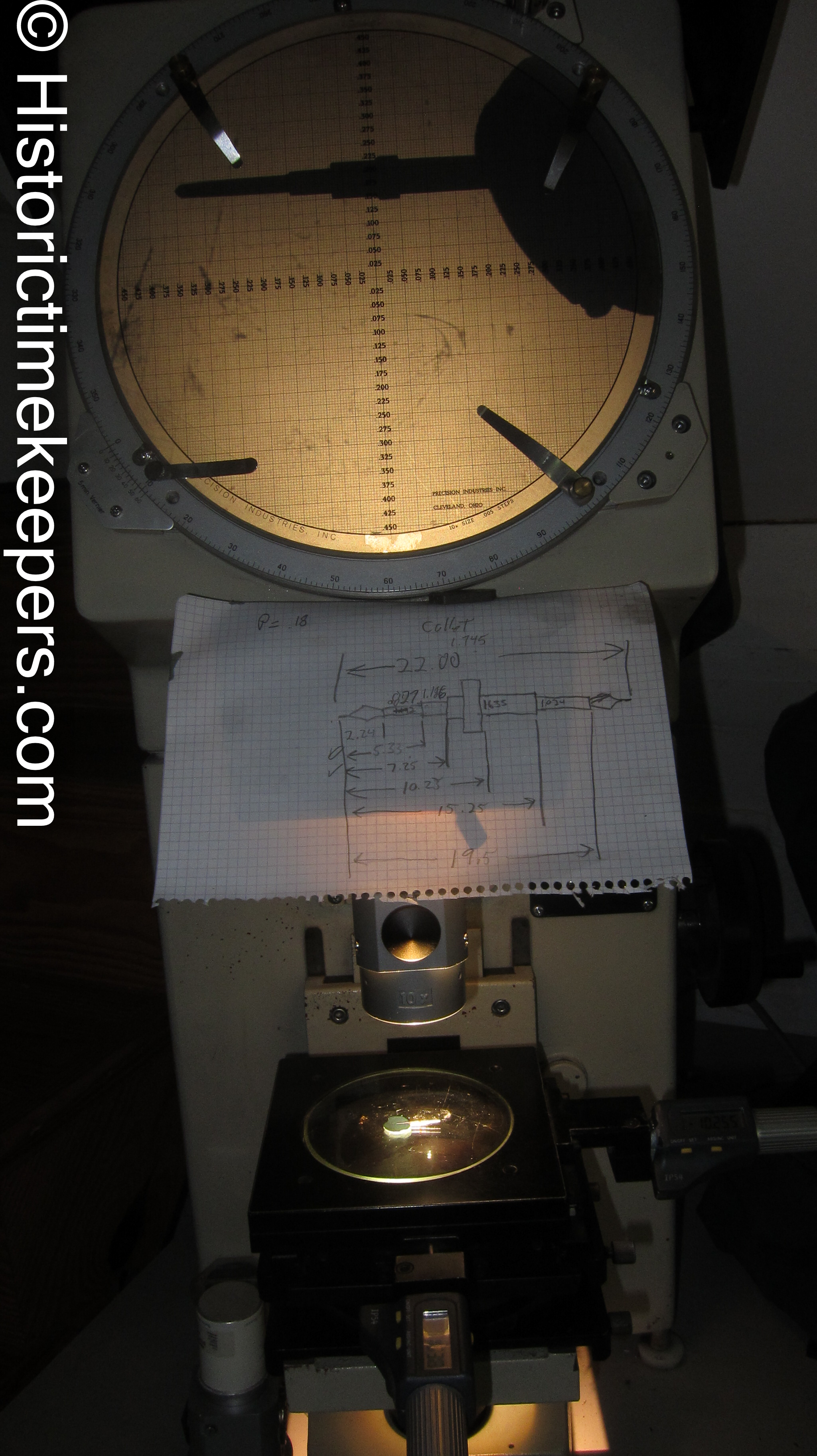
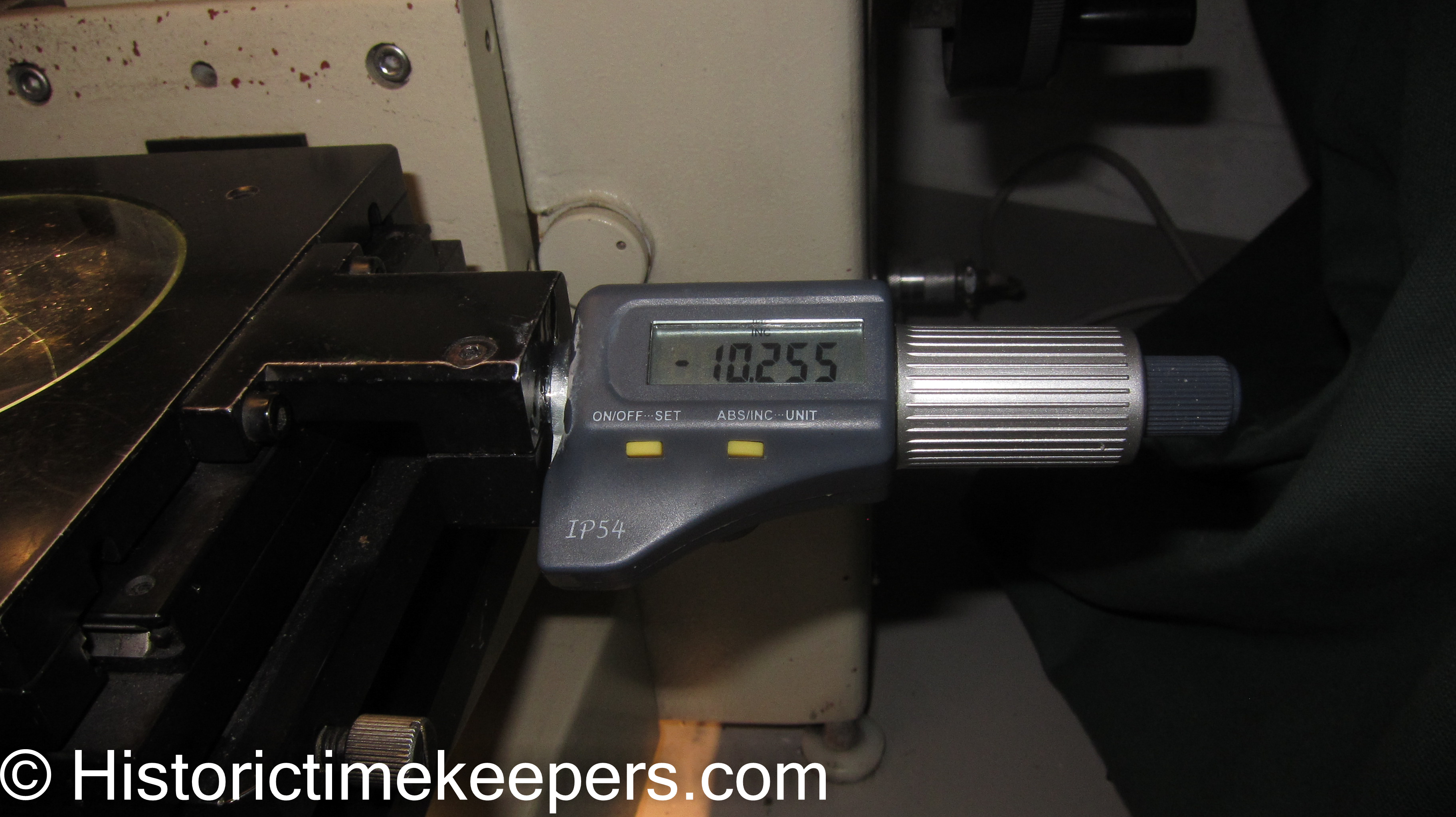
Optical Comparator My measurement instrument of choice for most work is the optical comparator. By fitting it with digital micrometer heads, I can easily measure lengths and diameters. The Nikon V10 I use was purchased on eBay for $500. While you will not find these falling out of the sky at this price, like everything else if you know what you are looking for, you will eventually find one at your price. With an optical comparator you can even measure angles!!
Determining Parallelism is an important function. In a similar vein, determining taper on a turned surface (like a balance staff) is also critical. There are two ways to do this. The first is to examine your turned part under magnification while held in the carbide tipped jaws of your micrometer. The light will reveal back taper, front taper, barrel, and dips. If no light is evident, then it is parallel. The other way is to use the optical comparator.
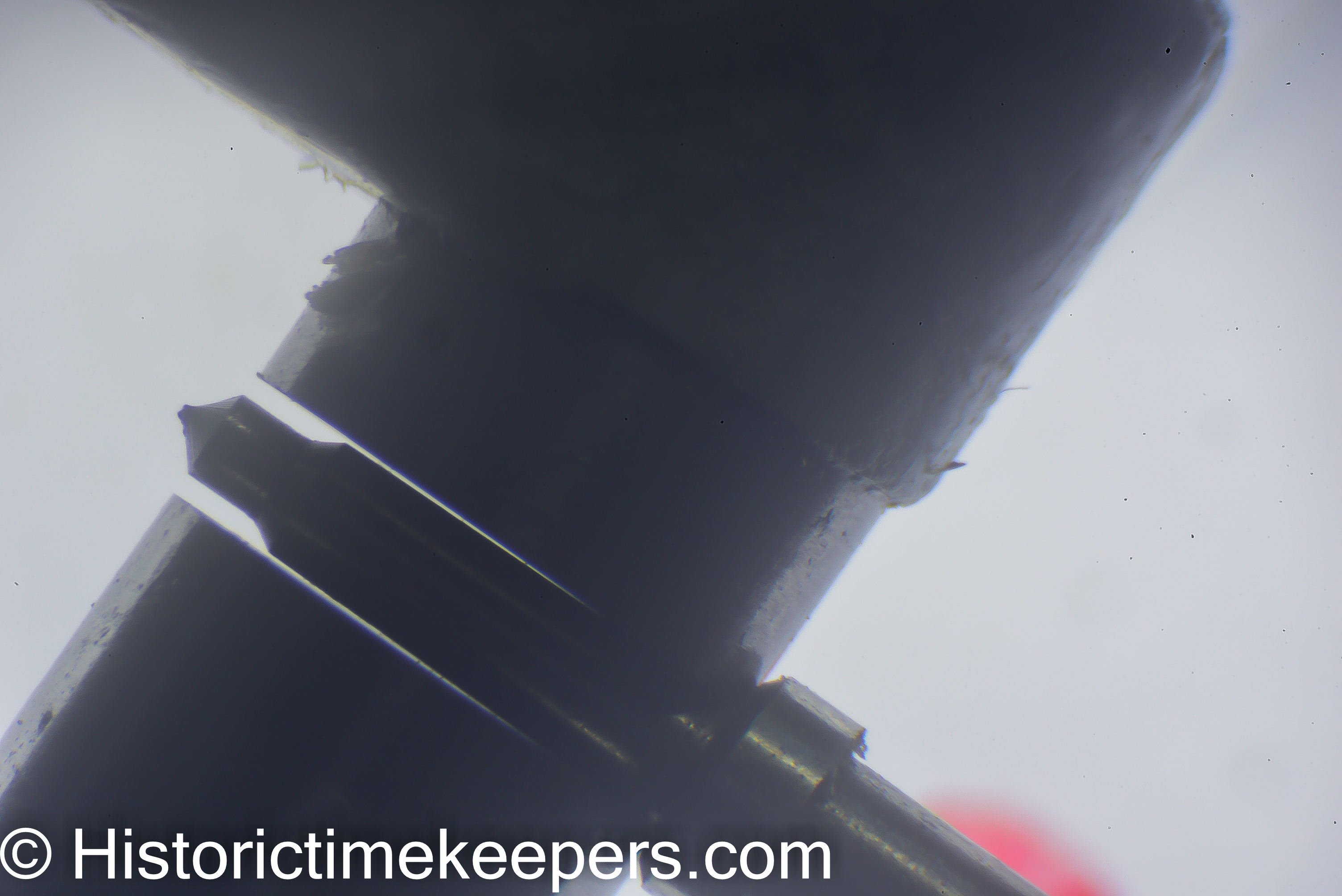
While on the lathe, I use the micrometer. For verification I use the optical comparator.
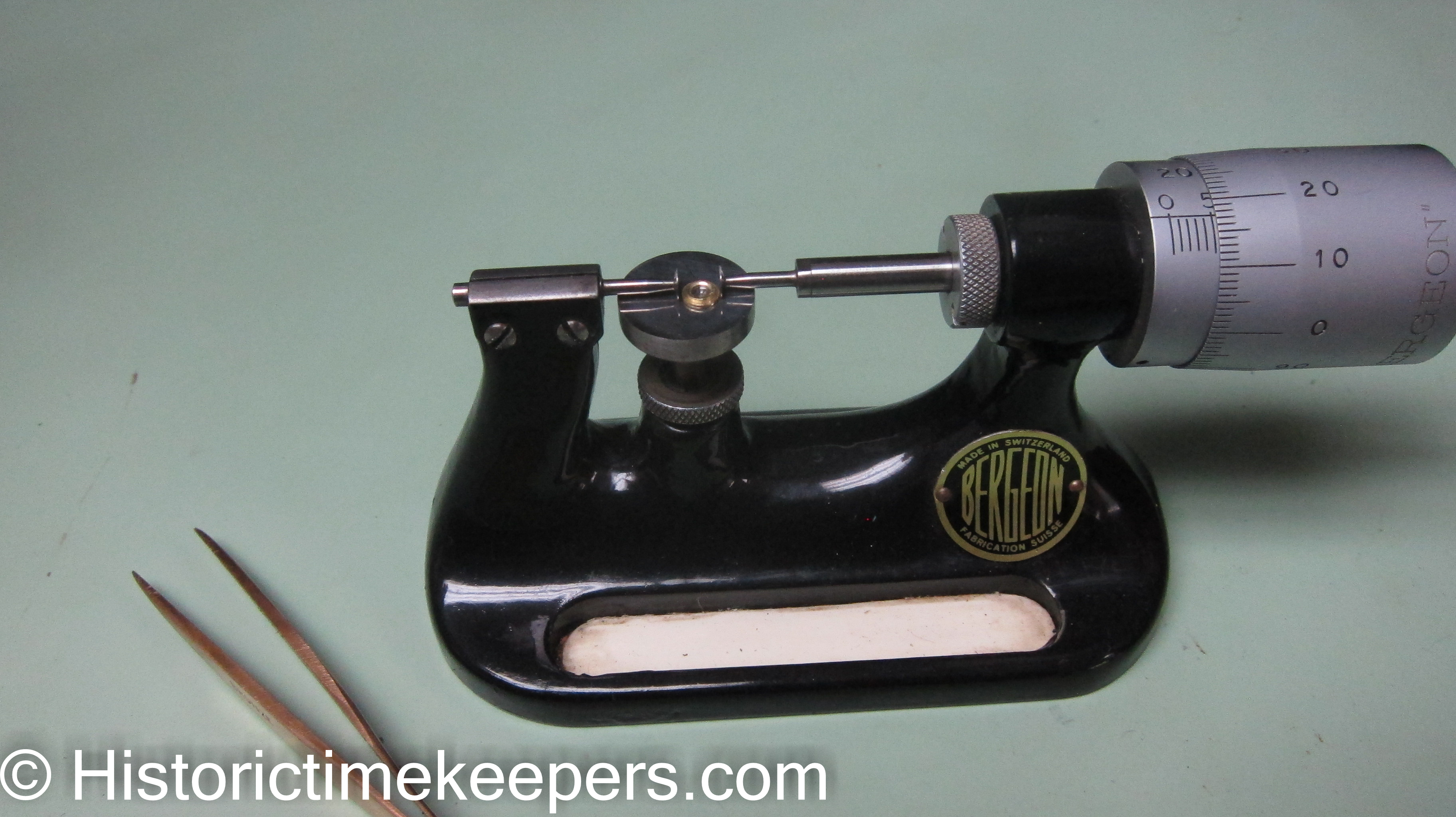
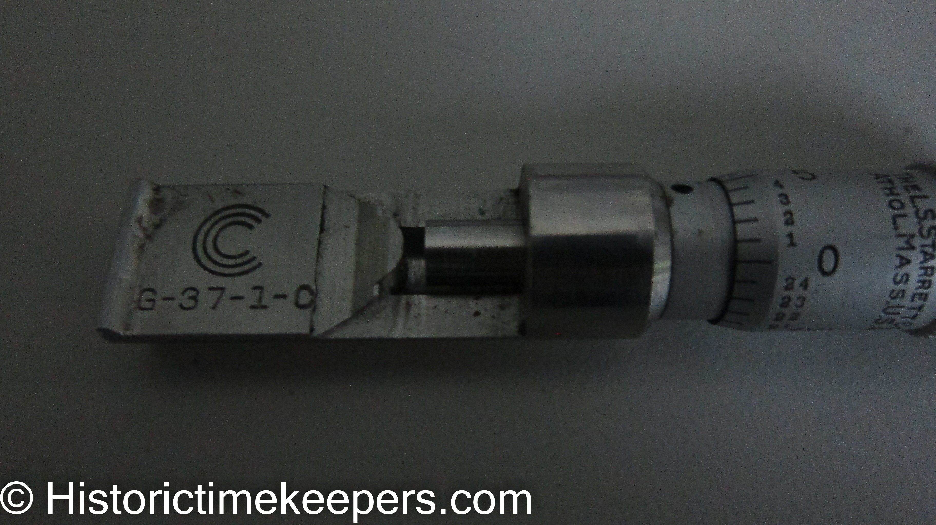
Some Other Measurement Instruments of occasional use are the Can seam micrometer, useful for measuring thicknesses of objects that are circular (like clock mainsprings). As you can see, the anvil is convex so that it has to measure on the tangent of the curved surface.
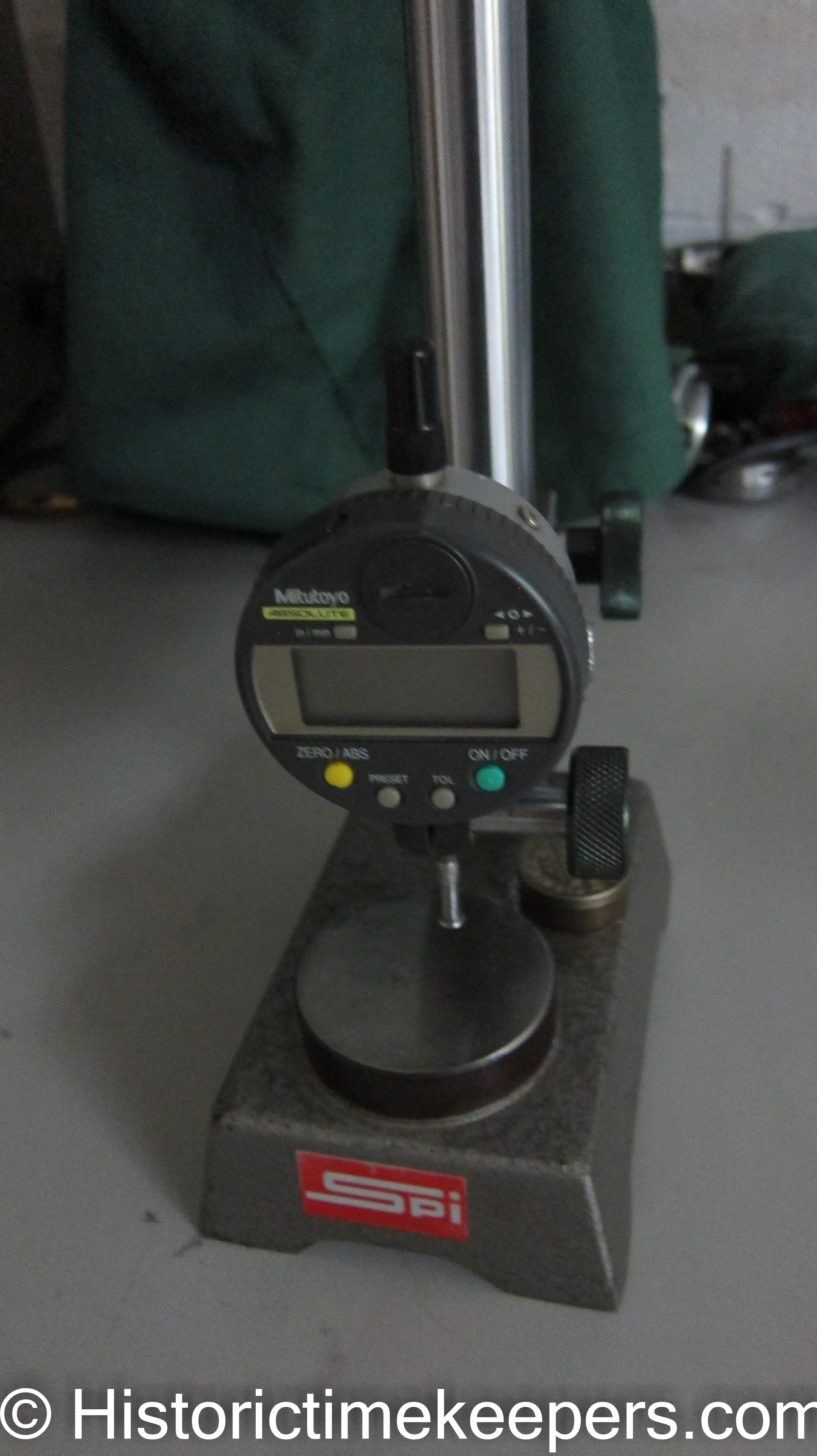
The Height gauge is what we used in class in Switzerland to measure lengths. You need to find or make an "elephant foot" tip so you can get at shoulders properly. It works well but you need to ensure your anvil is ground flat and parallel or you will not get reliable measures.
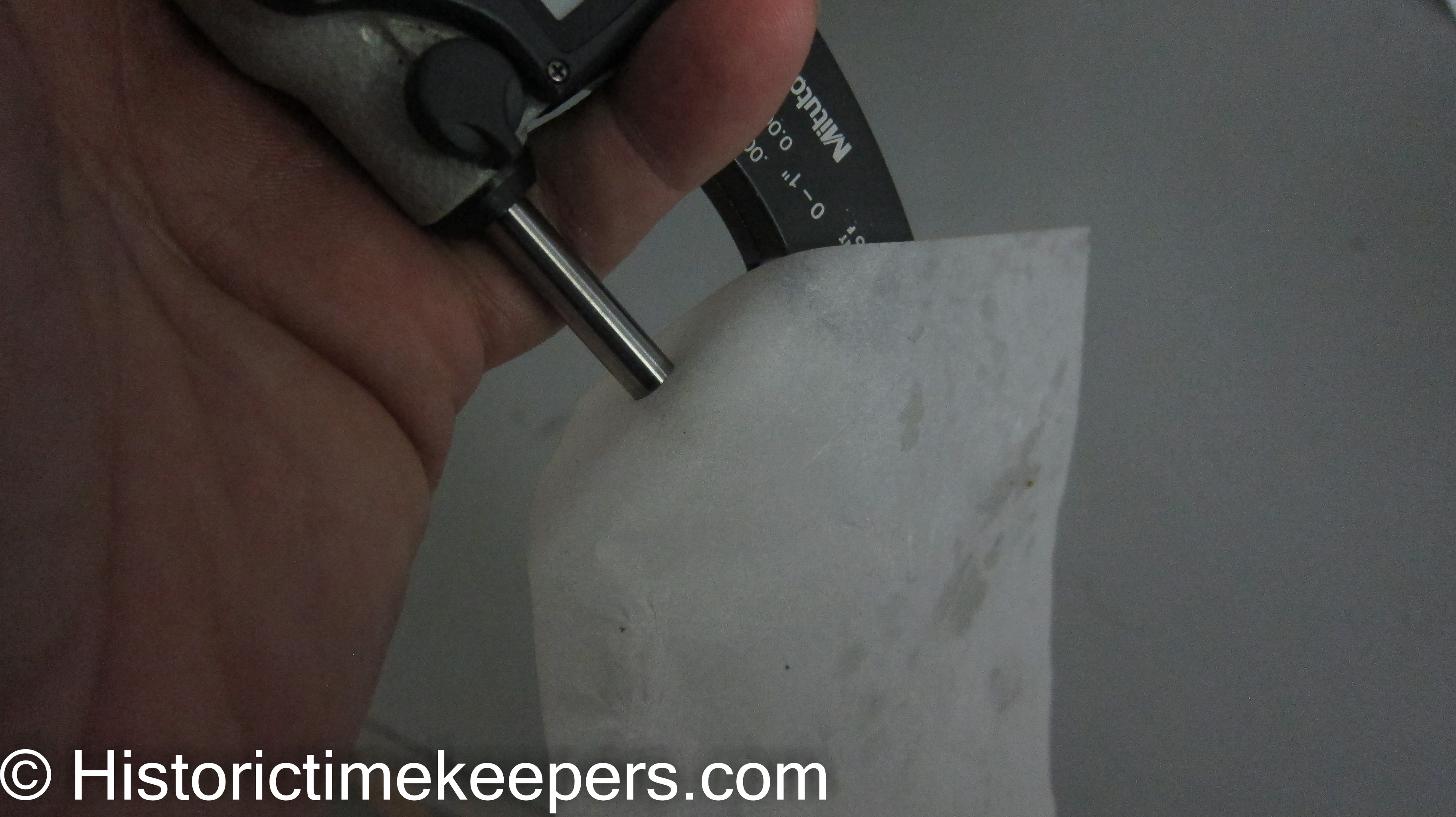
Rules for Precise Measurement include such things as making sure your piece is clean! Also the faces of your measurement instrument must be clean; "measure" a piece of tissue paper between the jaws and pull the tissue out. This will clean the jaws. Make SURE you zero the instrument! Also, develop a consistent touch. This is serious; do NOT rely on the ratchet safety device. The operative word there is "safety"--it is not to be relied on. In the old days, a journeyman machinist spent weeks if not months developing his touch that would enable him to transfer measurements from an outside caliper to an inside caliper and get both measurements to reconcile. Get into the habit of feeling when you have a sliding fit on your work!
The Datum is the "zero point" from which every length is taken. DO NOT turn a length, then measure the next length from the end of that one and so on. By the time you are done, you can easily be 20 or 30/100mm off and will have no idea where you went wrong. (Here think through the error inherent in using thickness gauges and being off with each measurement.) Pick one end of the staff, measure the length to roller hub from there. Then measure the length to the balance seat from the original starting point. And so on. This avoids cumulative errors from building up and while a length may 2/100 mm off, the total length will be within tolerance.
Make Your Drawing on the same plan. Starting from one end of the staff, dimension the distance of each turning from that one end. Put the ODs of each turning within the relevant section of the drawing. Then you have a turning plan you can use at your lathe with everything in one place. All lengths can be measured from one point and you know the ODs you need for each section.
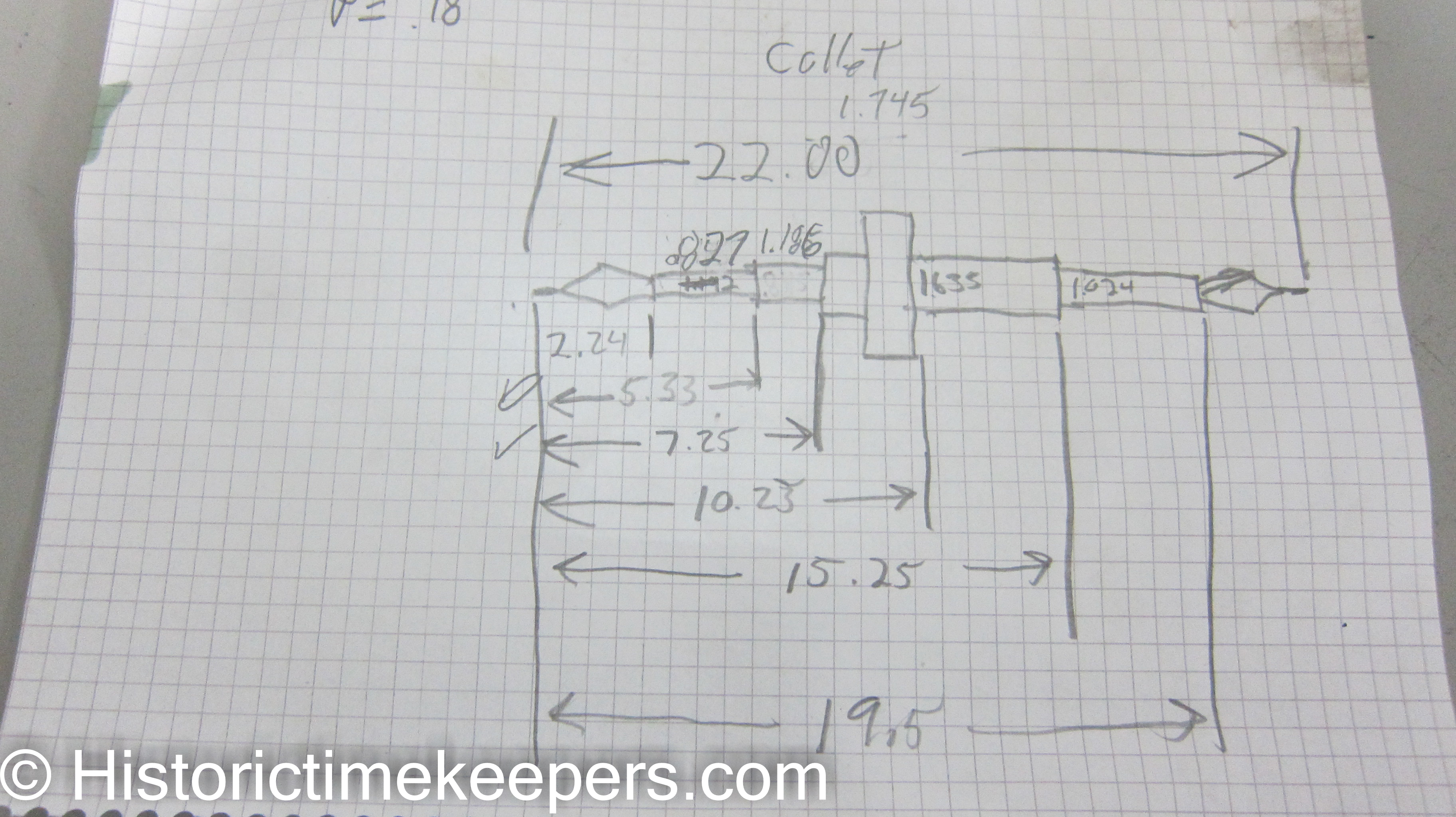
You will note when I make my plans, I record my dimensions in decimal values. This is the most efficient way to indicate metric dimensions. I only used fractions on this page to avoid confusion!
IF YOU FOLLOW this plan, you can then turn your staff blank to length (maybe leave it 5/100mm long), coat it with a Permanent Marker and then mark off your lengths with a 45 degree cutter in the slide rest or with the graver point.
Obviously, I am a strong proponent of turning between dead centers. Because work in progress on a dead center lathe can be removed and returned any number of times or turned end for end and retain accuracy, measurement and cutting is easy. A bit more of a challenge is using collets. When you reverse the work in a collet, you must choose one of the already turned sections to use as your new datum. Will introduce an error, but it will be small.
While my Horia turns was another tool I fell into, there are any number of ways to create a dead center turning setup. It is just for a number of reasons, the Horia is the most convenient and efficient. I recommend anyone interested in restoration work to come up with a dead center turns.
Below is how I prepare my work space and have all measurement instruments and the drawings at hand. Note the drawing is held onto the microscope post with a magnet for easy reference.