Popular Highlights
When only a watchmaker will do
Restoration of Omega Jump Seconds Clock
|
Making a Clock Pinion | 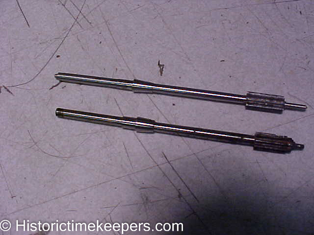 Finished new pinion above and rusted original pinion below |
||
This series shows the making of a clock pinion for a very early Smith's fusee marine lever bulkhead clock. This clock required extensive restoration including grinding new pallets, cutting a new escape wheel and extensive repivoting. It is yet another example of what happens when someone attempts "hit or miss" adjustments without knowing precisely what to do. The English covered pallets were "ground" for some kind of adjustment and the escapement was hopeless. This clock is one of the earliest Smiths marine levers and the owner wanted it restored to function. I wish I had before pictures and I apologize for the lack of photos showing the pallet making. The pinion was badly rusted and unuseable. I always cut two good pinions. One from brass and the final one from steel. This is because pinion cutters wear fast because they are cutting steel and the setups need to be precise. If the cutter is off center just a hair the pinion will be useless. So, I make one from brass, ensure it is correct, lock the machine settings and then load steel.
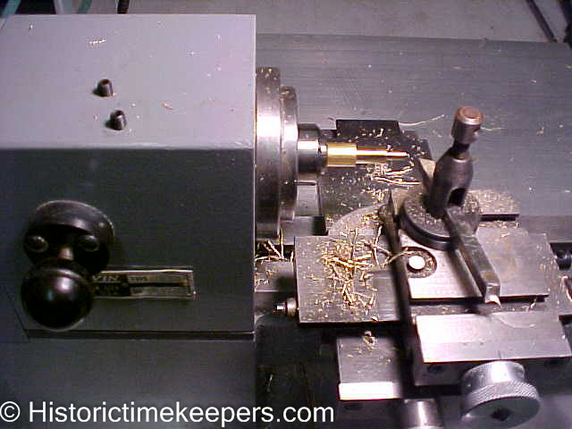
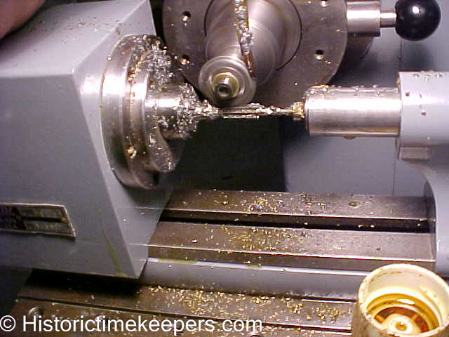
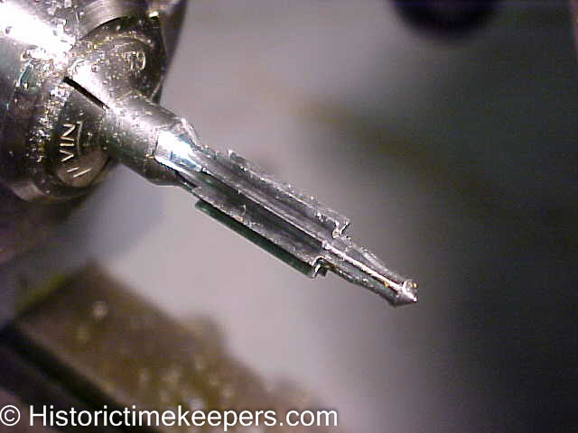
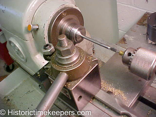
The next few shots show making the brass pinion.
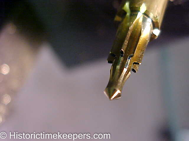
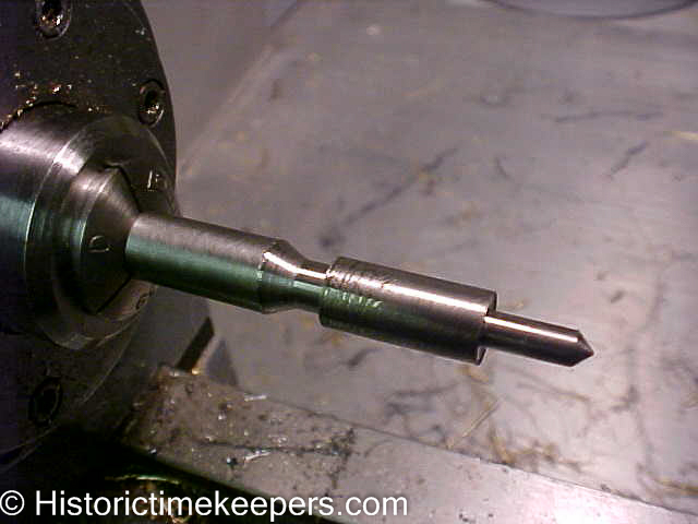
Now a steel blank is prepared to the correct diameter and the pinion is cut.
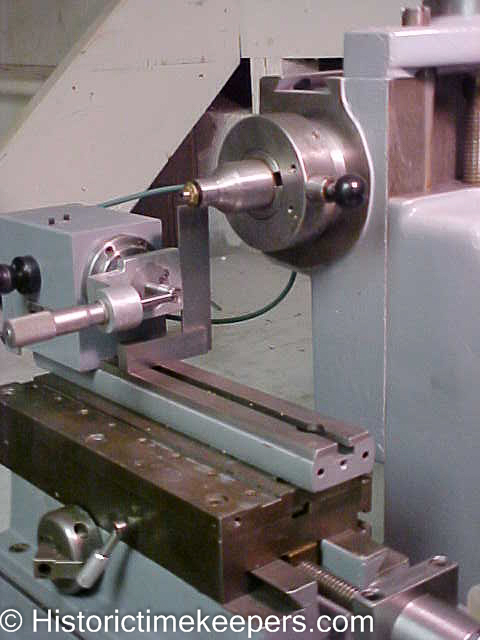
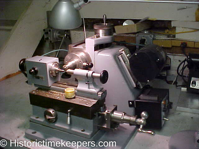
Because this pinion carries the friction wheel that drives the motion works (the center pinion is actually for the sweep seconds hand), it extends through the plates and is about 4 inches long. This is yet another reason the Habegger comes in handy.
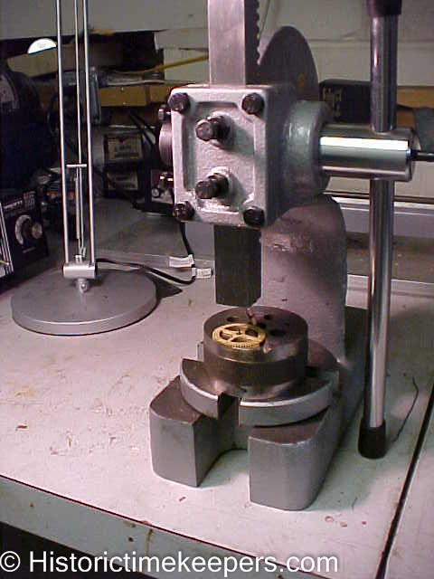
Pressing the wheel on the arbor.
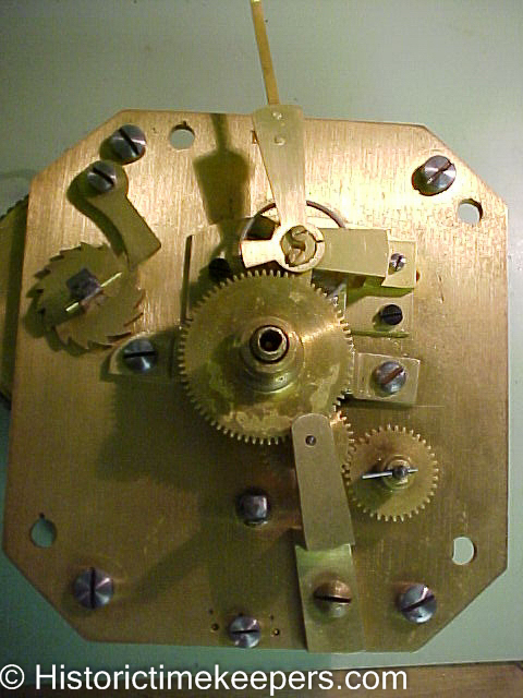
The pinion installed into the clock. It is carrying the wheel in the lower right hand corner that is driving the intermediate wheel.
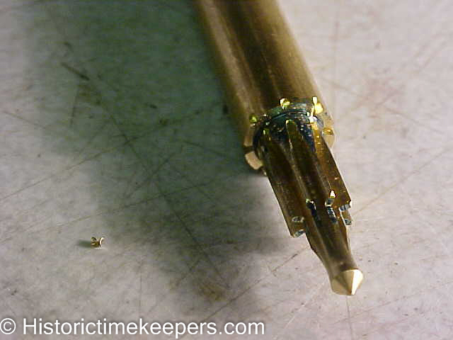
Here is a larger view comparing the old and new pinion. You may be better able to s the rut damage in the old (lower) pinion. The bearing above the shoulder is a different diameter because I rebushed the hole due to wear.
|
|||